cOS Demo System
Quick Start Guide
How to connect the cOS demo system to your network.
Lets get started!
Step 1: Connect The System To The AC Mains Power

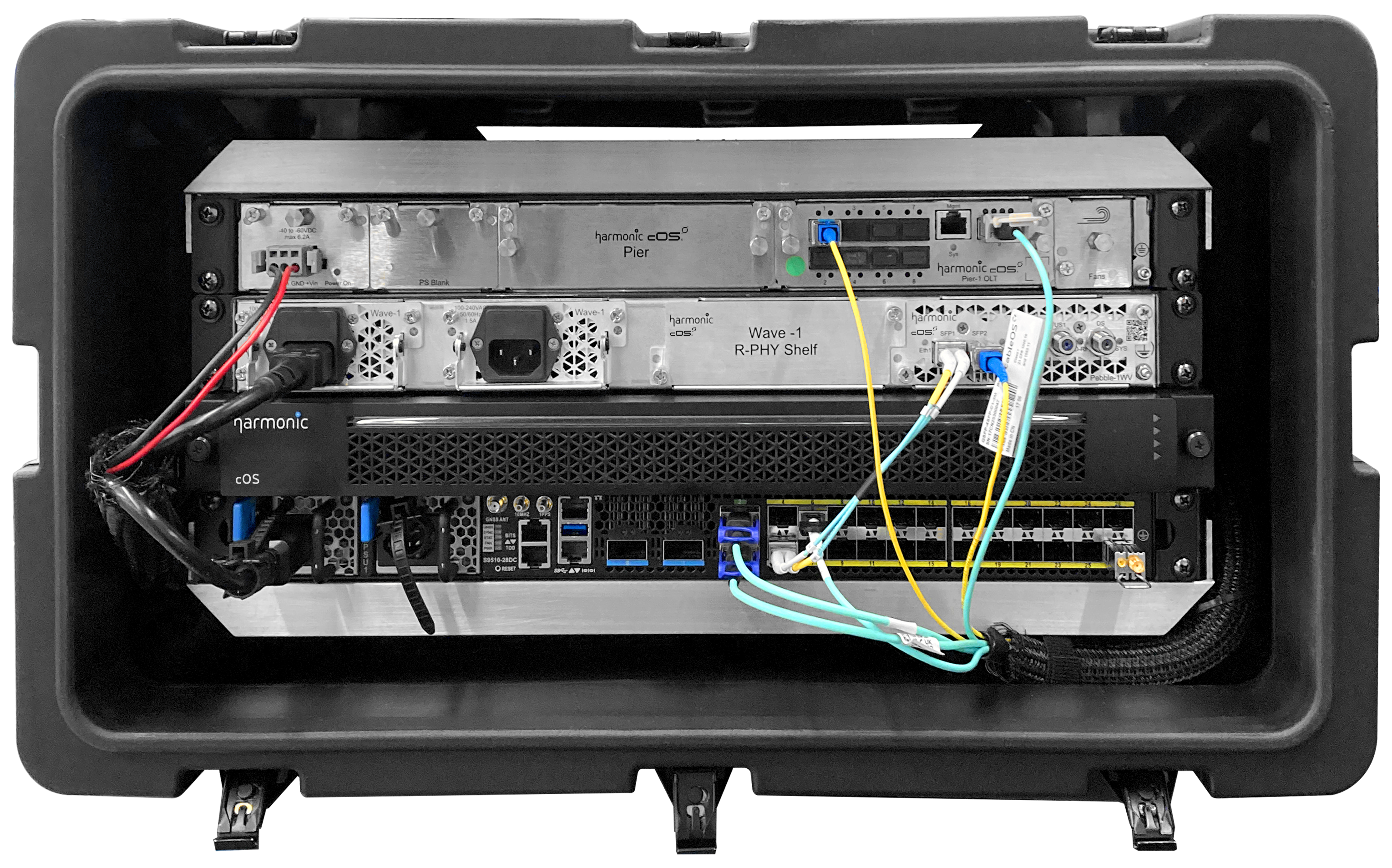
The demo kit is shipped in a portable standard 19 inches wide 5 RU height telecommunications rack. All the components in the rack come pre-wired. No rewiring is necessary.
Note: Peak system consumption is ~1kW.
1. Let the demo kit sit indoors for at least 2 hours before connecting AC power to avoid condensation build-up inside the rack that could be caused by potential temperature differences between the indoors and outdoors.
2. After the rack has acclimated to the indoor temperature, open the front and the rear doors of the demo kit.
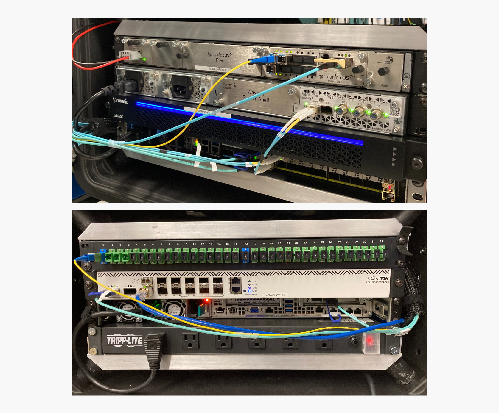
3. Locate the power distribution unit (PDU) at the rear of the kit.
4. Connect PDU to the main source of power.
Result: The demo system launches automatically.
5. Wait at least 30 minutes from power on for the cOS CLI to finish the launch.
Step 2: Connect The System To The Network

The router in the rack labeled NOMAD-GW-XX works as the system’s gateway to the network. It has NAT pre-configured on WAN interfaces, which conceals the internal cOS demo system networking from the operator's network for hassle-free networking integration.
Setup description: two SFP transceivers are pre-installed in router ports #1 and #2. You can use either SFP transceiver to connect the demo system to your network:
- Port #1 is 1Gbps copper SFP-T transceiver.
- Port #2 is 10Gbps SFP+ MMF (multi-mode fiber) transceiver.
Both interfaces are pre-configured with DHCPv4 clients to obtain the following IPv4 configuration from operator's network:
- IPv4 address.
- Network mask.
- Default gateway.
- DNS server IP address (optionally).
- If DNS server IP is not provided by the DHCP server, the system will attempt to use publicly available DNS servers at 8.8.8.8 and 1.1.1.1.
Note: You can configure static IP address(es) on the router (see optional procedure below).
Optional Step: Configure Static IP Address On WAN Interface

To configure 10Gbps interface follow the instructions:
1. Connect your laptop to the OOB management port on the front panel of the router
2. Configure the static IP to 192.168.88.10/24 on your laptop.
3. Open your web browser and enter the URL http://192.168.88.1/.
4. Log in using the username and password printed on the label inside the front door of the cOS demo kit.
Example:

5. In the left-side menu, navigate to IP → Addresses
6. Click Add New.
7. Configure static IP address and netmask on the SFP28-1 or SFP28-2 interface and click "Apply" or "OK" button.
Warning: You may only configure the SFP28-1 or SFP28-2 interface. Do not change IP configurations of any other interfaces, which could result in breaking system functionality.


1. Add a default route by navigating to IP → Routes in the left-side navigation menu
2. Click Add New.
3. Enter a default route as shown in the example and click "Apply" or "OK" button (replace 10.99.0.1 with the default gateway accessible on the operator's network).

Result: At this point it should be possible to ping the IP address assigned to the WAN interface of the router from your network.
Step 3: Connect PON ONUs
The cOS demo kit comes with a pre-installed and pre-connected PLC splitter on the rear side of the rack.
- The cOS demo system’s optical budget is calculated to allow for directly connecting PON ONUs to the splitter (no additional attenuation is needed).
- Different PON modes for cOS demo kits:
-
- Kits with a 1RU Pier-1 OLT shelf are preconfigured to support GPON and XGS PON on the same splitter ports (combo mode).
- Kits with a Fin SFP-based R-OLT support XGS PON and 10G EPON. By default, Fin R-OLT is pre-configured for XGS PON. Please contact Harmonic if 10G-EPON configuration is needed.

1. Locate the fiber patch cords attached in a plastic bag inside to the rear door of the kit.
2. Connect the ONUs to the splitter using SC/APC-SC/APC fiber patch cords.
Optional Step: Connect DOCSIS CMs ONUs
Setup description:
- cOS demo kit comes without cabling and passives for 6 ft plant.
- The system is preconfigured to work in high split mode by default.
Requirement: Please make sure your 6 feet plant provides ~40db of attenuation and can support high split spectrum. - The demo kit is configured for internal DOCSIS provisioning (DHCP server, TFTP server, example basic binary CM configuration file).
Step 4: Connect CPE
 (image to be added into a laptop)
1. Connect test CPE to the CM and/or ONU UNI
- CPE will be provisioned automatically via DHCP
- System is configured to NAT CPEs to the Internet
Your step-by-step guide for launching
the cOS demo system
Thank you for your interest in Harmonic's cOS™ virtualized broadband platform and our plug-and-play demo system. By following the directions on this page, you'll be up and running in no time!
The cOS demo system is pre-configured to help you quickly connect to your broadband access network, whether it’s for a FTTx (10G-EPON, XGS and GPON) or DOCSIS network. With this hands-on opportunity to see the cOS platform in action, you'll gain unique insight into the system's ability to virtualize your network, provide an always-on customer experience and grow your business.
System Components
- 1x cOS core server (label: NOMAD-COS-XX)
- 1x Core Routing Engine (L3 router) (label: NOMAD-CRE-XX)
- 1x router with NAT and firewall for easy, quick integration to an existing network (label: NOMAD-GW-XX)
- SFP-based or chassis-based PON OLT (label: NOMAD-OLT-XX)
- 110V AC power distribution unit (PDU)
- PLC optical fiber splitter
- Fiber patch cords
- Optionally, DOCSIS Remote PHY Shelf (RPS) (label: NOMAD-RPS-XX)
- Optionally, PTP master clock in SFP form factor

Step 1: Connect System to the AC Mains Power
%20(12).png?width=670&height=555&name=Industry%20page%20(test%20VH)%20(12).png)
%20(11).png?width=670&height=555&name=Industry%20page%20(test%20VH)%20(11).png)
Step 1: Connect System to the AC Mains Power
The cOS demo system is shipped in a rugged flight case outfitted with a standard 19-inch wide, 5-RU height telecommunications rack. All components in the rack come pre-wired, no rewiring necessary.
Note: Peak system power consumption is ~1kW.
- Allow the flight case to sit indoors for at least two hours before connecting AC power. This will avoid condensation build-up inside the rack, which could be caused by temperature differences between the indoors and outdoors.
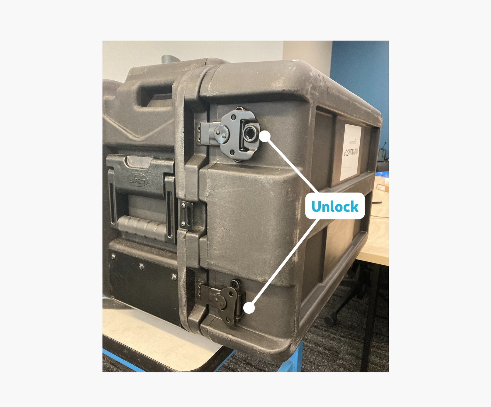
- After the system has acclimated to the indoor temperature, open the front and rear doors of the flight case.
- Locate the power distribution unit (PDU) at the rear of the system.
- Connect PDU to the main source of power. The demo system will launch automatically.
- Wait at least 30 minutes after powering on for the cOS CLI to become accessible.
Step 2: Connect System to the Network
Step 2: Connect System to the Network
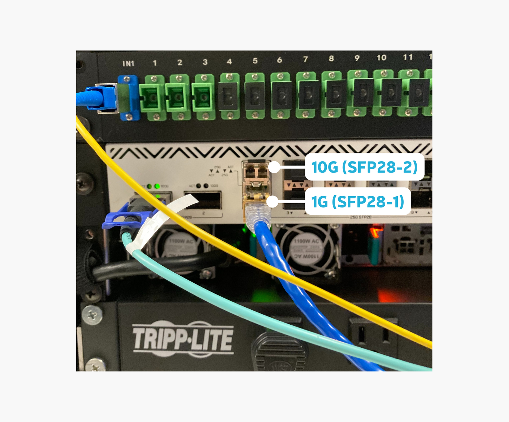
The router in the rack labeled NOMAD-GW-XX works as the system’s gateway to the network. It has NAT pre-configured on WAN interfaces, which conceals the internal cOS demo system networking from your network for hassle-free networking integration.
Setup description: Two SFP transceivers are pre-installed in router ports #1 and #2. You can use either SFP transceiver to connect the demo system to your network:
- Port #1 is a 1Gbps copper SFP-T transceiver.
- Port #2 is a 10Gbps SFP+ MMF (multi-mode fiber) transceiver.
- IPv4 address.
- Network mask.
- Default gateway.
- DNS server IP address (optional).
- If the DNS server IP is not provided by the DHCP server, the system will attempt to use publicly available DNS servers at 8.8.8.8 and 1.1.1.1.
Optional Step: Configure Static IP Address on WAN Interface
To configure 10Gbps interface:
Connect your laptop to the OOB management port on the front panel of the router.

Open your web browser and enter the URL http://192.168.88.1/
Log in using the username and password printed on the label inside the front door of the cOS demo kit.
Example:

Configure static IP address and netmask on the SFP28-1 or SFP28-2 interface and click "Apply" or "OK" button.
Warning: You may only configure the SFP28-1 or SFP28-2 interface. Do not change IP configurations of any other interfaces, which could result in breaking system functionality.


Enter a default route as shown in the example and click "Apply" or "OK" button (replace 10.99.0.1 with the default gateway accessible on the operator's network).

Result: At this point it should be possible to ping the IP address assigned to the WAN interface of the router from your network.
Optional Step: Configure Static IP Address on WAN Interface
1. Connect your laptop to the OOB management port on the front panel of the router.

2. Configure the static IP to 192.168.88.10/24 on your laptop.
4. Log in using the username and password printed on the label inside the front door of the cOS demo system.
Example:

5. In the left-side menu, navigate to IP → Addresses.
6. Click Add New.
7. Configure static IP address and netmask on the SFP28-1 or SFP28-2 interface and click "Apply" or "OK" button.
Warning: You may only configure the SFP28-1 or SFP28-2 interface. Do not change IP configurations of any other interfaces, which could result in breaking system functionality.


Result: At this point it should be possible to ping the IP address assigned to the WAN interface of the router from your network.
Optional Step: Configure Static IP Address on WAN Interface
To configure a 10Gbps interface:
1. Connect your laptop to the OOB management port on the front panel of the router.

2. Configure the static IP to 192.168.88.10/24 on your laptop.
3. Open your web browser and enter the URL http://192.168.88.1/.
4. Log in using the username and password printed on the label inside the front door of the cOS demo system.
Example:

5. In the left-side menu, navigate to IP → Addresses.
6. Click Add New.
7. Configure static IP address and netmask on the SFP28-1 or SFP28-2 interface and click "Apply" or "OK" button.
Warning: You may only configure the SFP28-1 or SFP28-2 interface. Do not change IP configurations of any other interfaces, which could result in breaking system functionality.


8. Add a default route by navigating to IP → Routes in the left-side navigation menu.
9. Click Add New.
10. Enter a default route as shown in the example and click "Apply" or "OK" button (replace 10.99.0.1 with the default gateway accessible on the operator's network).

Result: At this point it should be possible to ping the IP address assigned to the WAN interface of the router from your network.
Lorem ipsum dolor sit amet,
consectetur adipiscing elit nullam.
To configure 10Gbps interface follow the instructions:
1. Connect your laptop to the OOB management port on the front panel of the router
2. Configure the static IP to 192.168.88.10/24 on your laptop.
3. Open your web browser and enter the URL http://192.168.88.1/.
4. Log in using the username and password printed on the label inside the front door of the cOS demo kit.
Example:

5. In the left-side menu, navigate to IP → Addresses
6. Click Add New.
7. Configure static IP address and netmask on the SFP28-1 or SFP28-2 interface and click "Apply" or "OK" button.
Warning: You may only configure the SFP28-1 or SFP28-2 interface. Do not change IP configurations of any other interfaces, which could result in breaking system functionality.
8. Add a default route by navigating to IP → Routes in the left-side navigation menu
9. Click Add New.
10. Enter a default route as shown in the example and click "Apply" or "OK" button (replace 10.99.0.1 with the default gateway accessible on the operator's network).

Result: At this point it should be possible to ping the IP address assigned to the WAN interface of the router from your network.
Step 3: Connect PON ONUs
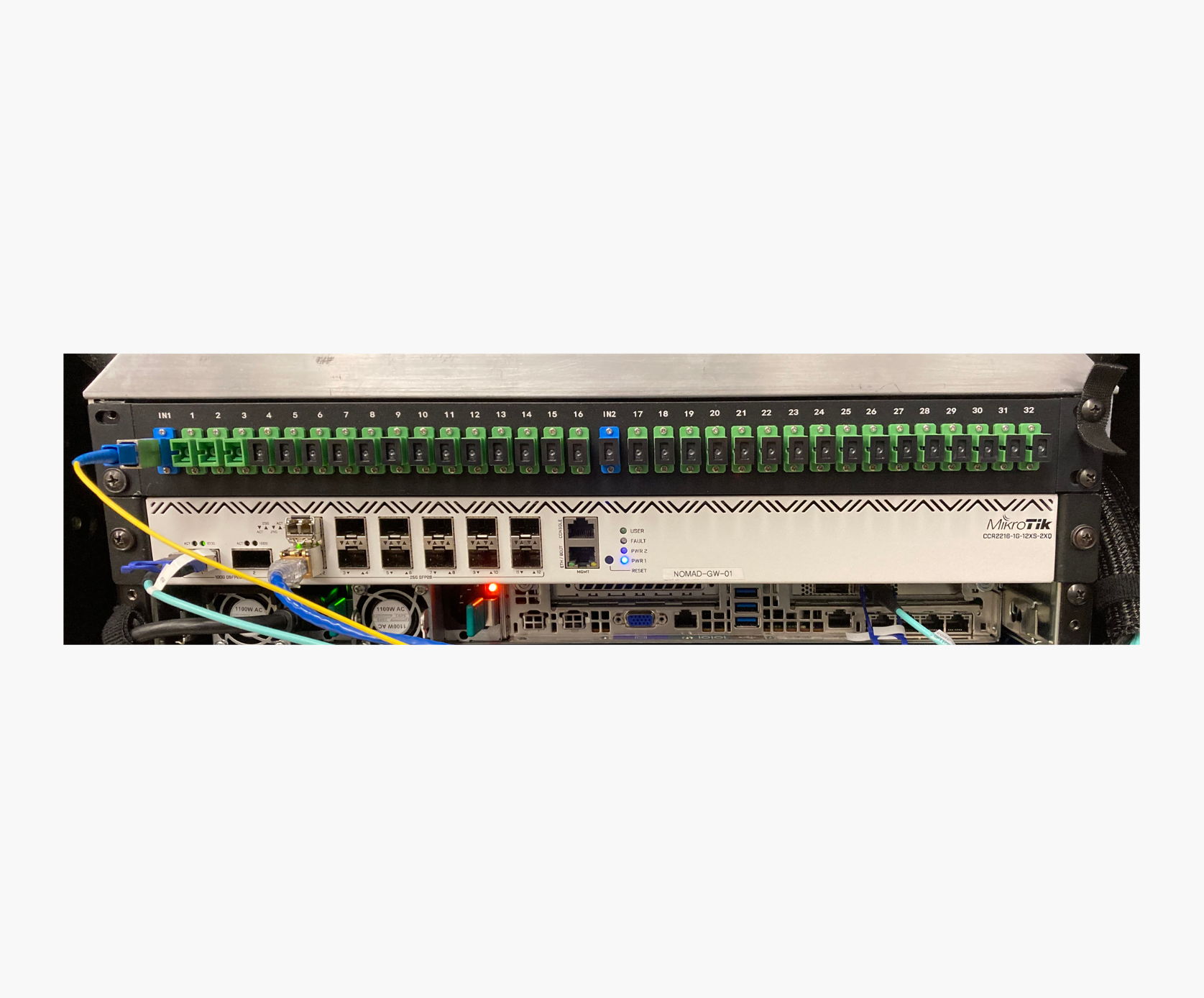
The cOS demo system comes with a pre-installed and pre-connected PLC splitter on the rear side of the rack. The system’s optical budget is calculated to allow for directly connecting PON ONUs to the splitter (no additional attenuation is needed). Different PON modes are used for specific cOS demo systems:
- Systems with a 1-RU Pier-1 OLT shelf are preconfigured to support GPON and XGS PON on the same splitter ports (combo mode).
- Systems with a Harmonic Fin SFP-based R-OLT support XGS PON and 10G EPON. By default, the Fin R-OLT is pre-configured for XGS PON. Please contact Harmonic if 10G-EPON configuration is needed.
- Locate the fiber patch cords in a plastic bag attached inside the rear door of the flight case.
- Connect the ONUs to the splitter using SC/APC-SC/APC fiber patch cords.
Optional Step: Connect DOCSIS CMs
-
The cOS demo system comes without cabling and passives for 6-ft plant.
- The system is preconfigured to work in high-split mode by default.
Requirement: Your 6-ft plant must provide ~40db of attenuation and support high-split spectrum.
-
The system is configured for internal DOCSIS provisioning (DHCP server, TFTP server, example basic binary CM configuration file).
Optional Step: Connect DOCSIS CMs
Setup description:
The kit is preconfigured to work in high-split mode by default.
Requirement: Your 6-ft plant must provide ~40db of attenuation and support high-split spectrum.
The kit is configured for internal DOCSIS provisioning (DHCP server, TFTP server, example basic binary CM configuration file).
Step 4: Connect CPE
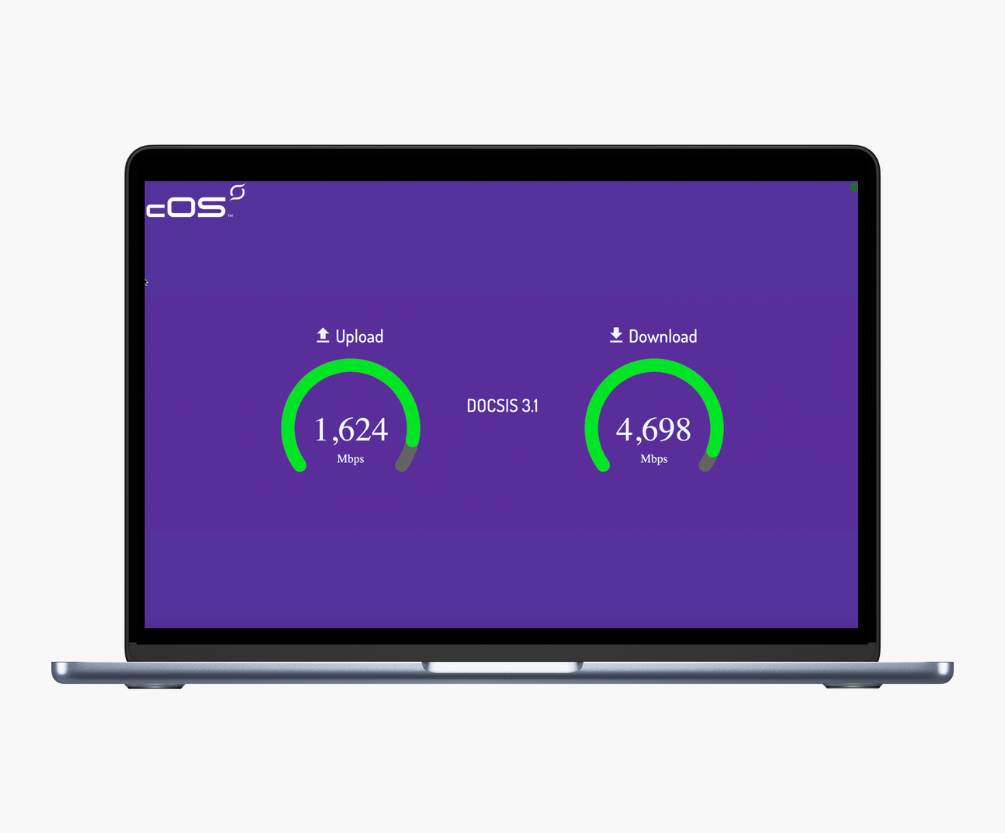
1. Connect test CPE to the CM and/or ONU UNI.
- The CPE will be provisioned automatically via DHCP.
- The system is configured to NAT CPEs to the internet
2. Use fast.com, speedtest.net or other tools to verify capabilities of the system.
Step 5: Verify System with cOS CLI commands
1. Using the password and TCP port printed on the sticker inside of the front door of the rack, connect to the cOS virtualized core platform via SSH.
2. In the SSH command, replace the letter X with the number of your demo system, located on the sticker of the system housing:
ssh nomad@pon-demo.cableos-central.com -p 220X
3. Execute the following CLI commands to verify system status:
-
-
- show pon olt
- show pon onu
- show pon vcm
- show cable rpd
- show cable modem
- show running-config
- show cluster status
-
Access cOS Central Analytics Dashboards
cOS Central offers a powerful family of applications for ensuring optimal network performance, including advanced streaming telemetry that provides real-time intelligence and AI-generated recommendations for proactively resolving issues before they affect service.
The cOS demo system is pre-configured to provide streaming telemetry, sending data in near real time to the secure cOS Central Analytics web application. Use the URLs from the email you received from Harmonic to access cOS Central Analytics dashboards for your demo system.
The examples below show dashboards in the cOS Analytics portal:
View the OLT dashboard
- Click here to open "cOS Central OLT (Details)" page.
- In the top left corner find a dropdown menu and choose your cluster (nomad-XX).
View the ONU Dashboard
- Click here to open "cOS Central ONU (Summary)" page.
- In the top left corner find a dropdown menu and choose your cluster
(nomad-XX). - Click on the ONU to see more detailed information about its state.
There are many other dashboards available in cOS Central Analytics, offering an in-depth view of every aspect of the cOS solution. Feel free to explore and discover the additional insights it provides. Click here to see a full list of available dashboards.
Need help or assistance?
For any questions you may have, please contact your Harmonic sales representative or email us at


